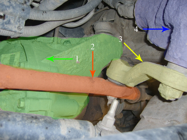
- Front Differential
- Track Rod?
- Pitman Arm
- Steering box
|
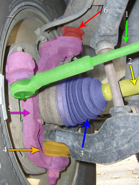
- Tie Rod
- Half Shaft
- CV Boot
- Lower Ball Joint
- Steering Knuckle
- Upper Ball Joint
|
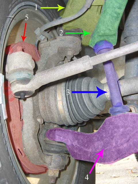
- Upper Control Arm
- Front Sway Bar
- Stablizer Link
- Lower Control Arm
- Brake Rotor
|
Front Passenger wheel removed:
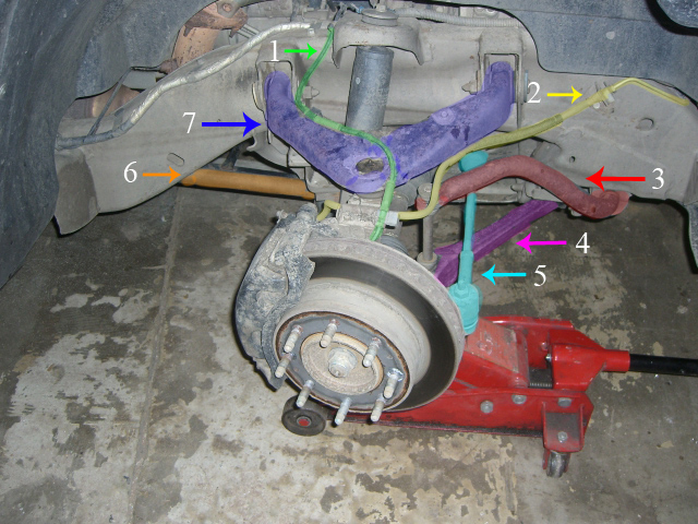
- ABS Line?
- Brake Line
- Front Sway Bar
- Lower Control Arm
- Tie Rod
- Torsion Bar
- Upper Control Arm
|
Same view as above, different parts:
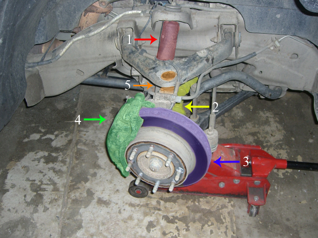
- Shock Absorber
- Half Shaft and CV Boot Covers
- Brake Rotor (actual braking surface highlighted)
- Brake Caliper
- Upper Ball Joint
|
Grease zerks, passenger front wheel removed:
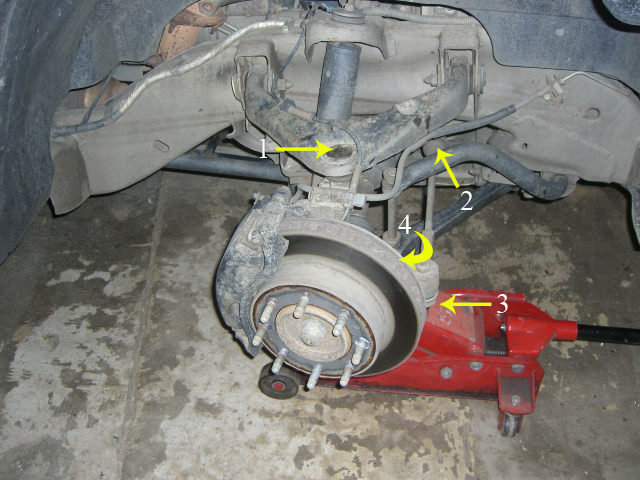
- Upper Ball Joint
- Idler Arm (in further than shown)?
- Tie Rod Attachment
- Lower Ball Joint (on bottom of lower control arm)
|
Closeup of passenger wheel assembly, looking into the engine compartment:
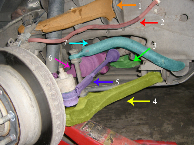
- Upper Control Arm
- Brake Line
- Front Differential
- Lower Control Arm
- Tie Rod
- Half Shaft and CV Boot Covers
- Front Sway Bar
|
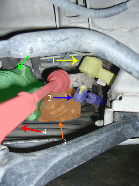
- Idler Arm
- Steering Stabilizer
- Front Differential
- Tie Rod
- Half Shaft and CV Boot Cover
|


